Report 001 - 30mm Crane Rope
Introduction
A site visit was conducted on 8 August 2017 and both ends of the failure were examined.
Crane Number 2 at CraneOpperations has a main hoist and two auxiliary hoists. The 85 ton main hoist is fitted with a 320m, 30mm 8 strand rope with an independent wire rope core. The rope failed catastrophically.
The main hoist is reeved with 12 falls and a centre compensating sheave and the rope ends are attached to the drum. The sheaves have a root diameter of 610mm.
The groove profiles on the drum, top sheaves and on the bottom block were inspected and were measured to be 31,5mm which is within standard recommendations. The compensating sheave was inaccessible and could not be checked or inspected.
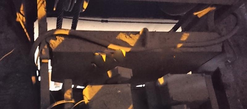
Photograph 1. Shows the boxing and mounting of the compensating sheave in the crane cross travel. The sheave is boxed in and hangs below the floor level of the cross-travel carriage.
Observations
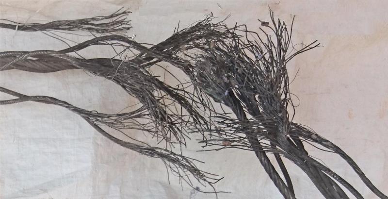
Both ends of a broken rope were examined. The examination showed that the ropes had been mechanically damaged at the point of failure as detailed in the following photographs:

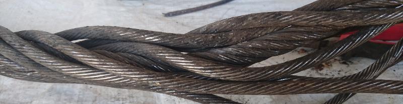
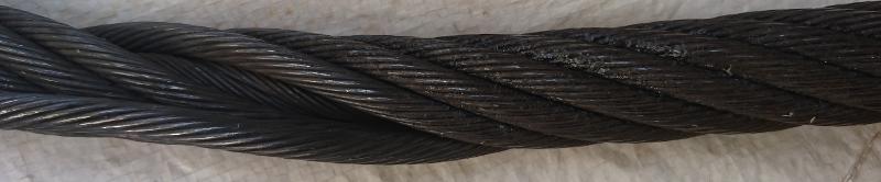
Photograph 2. Shows an overview of the failed section of the rope. There are two separate and distinct locations of severe wire damage located at 600mm apart. The length of both damage sections is 120mm. The rope at the damaged location has been pulled into a curve tighter than the natural curve of the rope. The red ellipse indicates where the compensating sheave would have been.

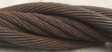
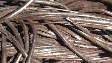
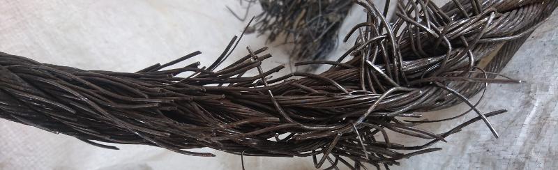
Photograph 3. Shows the left-hand section of damage. The damage is characterised by numerous fatigued wire breaks which are detailed below. There is no lubricant in this section of rope and significant fretting corrosion.
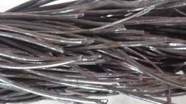
Photograph 4. Shows the right hand damaged section of rope which failed catastrophically. The wire fractures are all fatigue related.
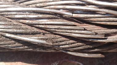
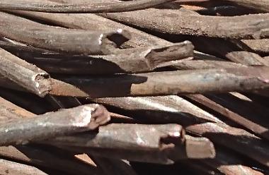
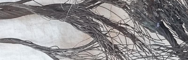
Photograph 5. Shows outer wires exhibiting battered fatigue where the wires have started fatiguing and were then subjected to repeated bashing.
Photograph 7. Shows a cluster of fatigued wires near the rope failure position.
Photograph 6. Shows outer wires which have fatigued due to repeated loading and unloading.
Photograph 8. Shows wires which have fatigued and products of fretting corrosion (rust).
Lubrication
The following photographs detail the degree of lubrication in the region of the rope failures. Using photograph 1 for reference, from the left-hand side at 600mm from the first point of damage the lubrication was assessed to be deficient. In the damaged section, the lubrication was assessed to be dry. Between the damaged sections the lubrication is deemed deficient. In the second section of damage (the point of failure) the lubrication was again deemed to be dry. 600mm Further the lubrication was deemed to be deficient. (Reference 1)
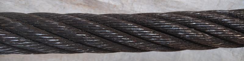
Photograph 9. Shows the lubrication of the rope 600mm before the first point of damage.
Photograph 10. Shows the first damaged section where the lubrication is assessed as being dry.
Photograph 11. Shows the section of rope between the damaged sections where the lubrication is assessed to be deficient.
Photograph 12. Shows the second damaged section, the point of failure, where the lubrication was assessed to be dry.
Photograph 13. Shows the rope on the right-hand side of the point of failure. The lubrication was assessed to be deficient.
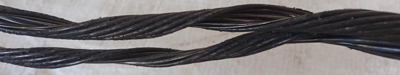
Photograph 14. Shows a strand which was opened to expose the inner wires. The lubrication was assessed as dry.
Findings
The wire failure was due to fatigue.
The lubrication of the rope was assessed to be deficient to dry around the failure.
There were significant amounts of rust caused by fretting corrosion in both sections of damage.
The wire breaks included simply fatigue, stepped fatigue and battered fatigue.
Knock on mechanical damage was also noted. This occurs when a broken wire (or wires) are bent over other wires and pushed into them causing indentations and stress raisers.
The distance between the two points of damage coincides with the diameter of the compensation sheave. This indicates small movements of the rope on and off the sheave during operation.
The points of contact with the sheave are also the points at which vibration is taken out of the rope and is a node point for vibration.
The contact point of the rope with the sheave is also subjected to high compressive forces as well as the tensile load that is carried by the rest of the rope.

Rope deterioration profile
A steel wire rope operating on a crane is subjected to varying loads and degrees along its length.
The rope end is attached to the drum and a short length of rope is subjected to a generally static tensile load for three or four wraps. A length is then subjected to tensile and bending fatigue loads as it winds on and off the drum. Another length is also wrapped on and off a sheave and so the fatigue conditions increase along the length of rope. Depending on the configuration of the lifting system and the distance between the sheaves a fatigue profile of the system can be developed.
The reeving on crane number two is a 12 fall system as shown in the sketch to the left. It can be evaluated as two six fall systems, the left hand side mirroring the righthand side. The deterioration graph for a six-fall system is shown on the next page:
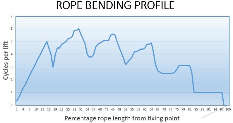
Graph 1. Shows the hypothetical rope deterioration along the rope length (for one side of the hoisting system of crane No. 2). The left-hand side of the graph shows the deterioration of the rope that is fixed to the drum and the right hand side for the rope that passes over the compensating sheave. (The fatigue on the compensating sheave is not included in this hypothetical analysis.) This analysis is based on the crane lifting the load from the bottom position to the 25% of the total lifting height for 25% of the lifts, to 50% of the height for 25% of the lifts, 75% of the height for 25% of the lifts and the remaining 25% of the lifts to full height. This shows that the most significant wear will occur between 16m and 80m from the drum ends.
Rope temperature profile in hot work facilities
A rope operating in a hot work environment will be exposed to furans blast heat when the crane collects the crucible from a furnace. Once the furnace doors close the temperature of the rope will decrease. This cyclic heating and cooling of the outer wires of the rope will cause the internal temperature of the rope to rise during operation. Depending on the intensity of the heat and the duration of the cycle the internal rope temperature may rise to certain critical temperatures. This upper temperature limit will place boundaries on the rope selection criteria limiting the potential rope selection or requiring specialised ropes to be used.
A hypothetical rope temperature is shown below:
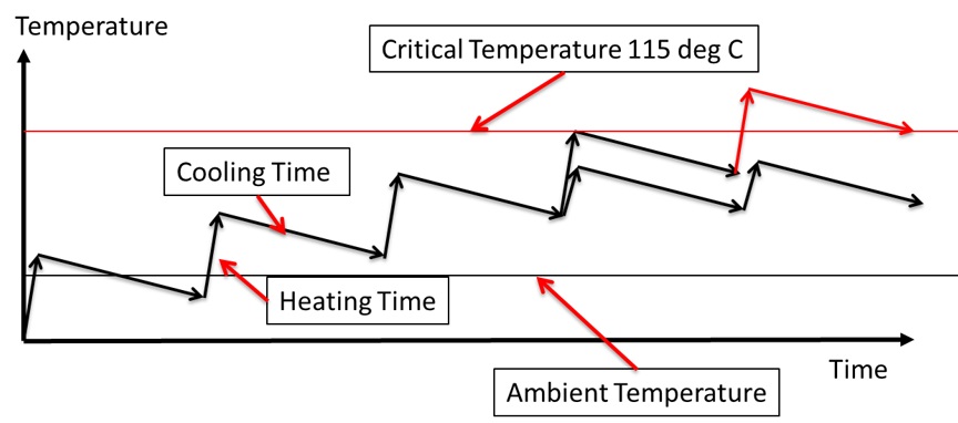
Graph 2. Shows a hypothetical rise in temperature of a rope operating in a hot work environment.
The first critical temperature encountered is at 115˚C the temperature at which a rope with plastic components cannot be used.
The next temperature barrier to be considered is the temperature at which the lubrication deteriorates. This will depend on the lubricant applied to the rope and will vary from product to product.
The final critical temperature to be considered will be that at which the steel structure begins to change and this will be at around 350˚C.
This analysis should be done in real time to determine what the actual operating temperature of the rope is and what boundary conditions are being encountered.
Conclusion
The rope failure occurred due to fatigue of the wires at the point at which the rope contacted either side of the compensating sheave.
Lack of lubrication contributed significantly to the breakdown of the wires.
Recommendations
Rope inspection
The fixing of the compensating sheave makes for a very difficult inspection of the rope at this point. Despite the difficulty of accessing the sheave, inspection of the rope in this region should be included in the weekly rope inspection. This may be facilitated by manually pulling the rope to ground level for the inspection or using a cherry picker to inspect the rope in position. Alternately the compensating sheave fixing could have inspection hatches built into it.
Rope lubrication
The rope should also be lubricated on a regular basis. A heat resistant oil based lubricant should be considered because the rope at this point is under constant load which prevents a grease based lubricant from penetrating into the strands. An oil will be drawn in by capillary action.
The rope could be lubricated by hand during inspection when it has been pulled to ground level of a drip/spray could be used at the compensating pully.
Rope end cuts
Cutting a length of rope from one end the major fatigue points will be moved through the system. This puts less damaged areas into the high wear zones and the damaged sections into less arduous working points. This could increase rope life significantly. This will be particularly beneficial where the rope passes over the compensating sheave. This could be done at periodic intervals to coincide with maintenance shutdowns.
References
- Modes of rope deterioration (Reference booklet) by M Borello – SIMRAC
- SANS4309 Crane Rope Maintenance and Discard
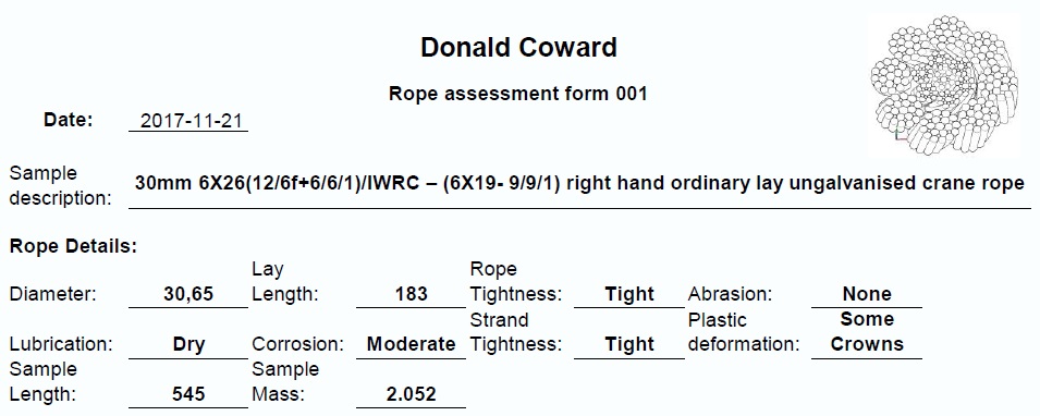
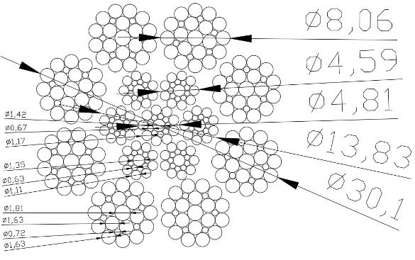
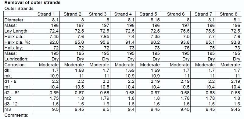
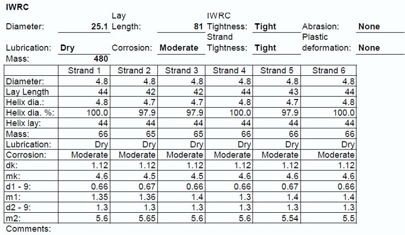
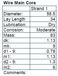
Measured rope properties