INTRODUCTION
ROPE DESIGN
A starting point for steel wire rope design is looking at what combinations of round wire present stable configurations.
A single round wire, when small in diameter will be stable and flexible but as the diameter increases the flexibility is lost. As wires are added the flexibility increases but the stability of the “bundle” of wires needs to be assessed.
Two wires are neutral as the position of the wires will always be the same regardless of the rotation of the cross section. There is only one point of contact.
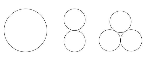
Three wires are stable as the interacting forces between the wires will always form a triangle – each wire has two points of contact and the distance between the axis of the wires will always be at a minimum.
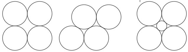
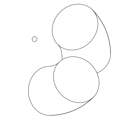
Four wires is unstable. Although each wire has two points of contact the points of contact can move and is shown in the following sketches. For a “four” wire strand to be stable a small fifth wire needs to be added as a core to provide support for the wires and prevent the construction from collapsing. Thus a four wire strand will become a five wire strand. From this point, strand shape is dictated by the geometry of round wires, and as larger more flexible strands are required more wires are added.
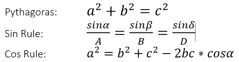
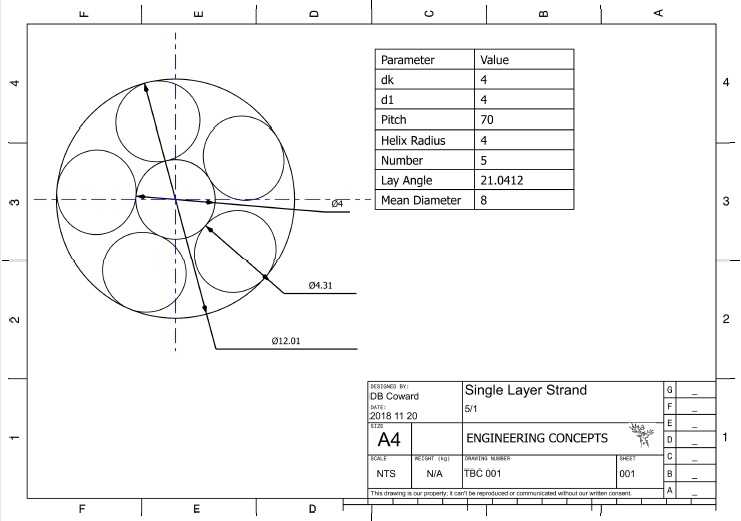
The above discussion of a five wire strand illustrates the need to calculate the relative wire diameters of the wires in a layer and the diameter of the supporting wires. This can be done mathematically with simple geometric calculations:
Wire diameter calculation
Basic trigonometrical equations
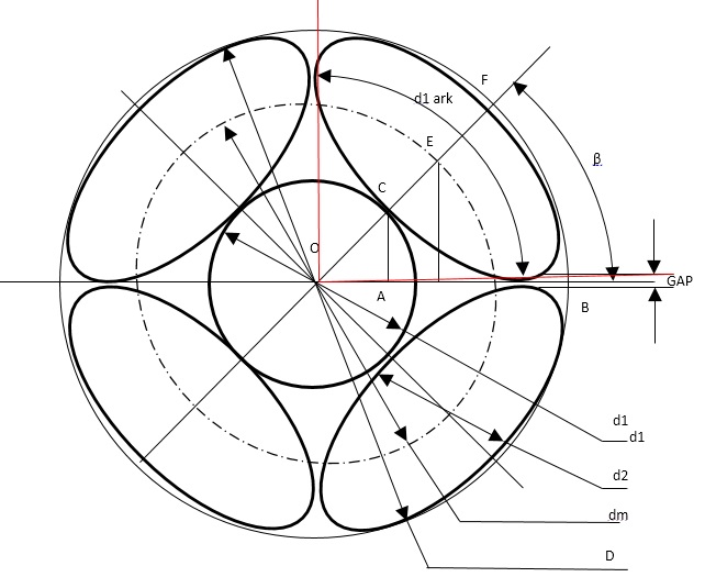
FOUR OVER ONE CONSTRUCTION
The strand diameter D = d1 + 2d2
The number of wires in the layer = N = 4
The center angle = β = π/N
The mean diameter dm = d1 + d2
The strand diameter is then ds = dm + d2
By manipulation of the above equations we can then calculate the wire sizes and strand diameters required.

Why wires are twisted together
The above equations only hold true if the wires are laid parallel to each other and to the axis of the strand. The limitation of the circular theory is that ropes are to be used on drums and around sheaves and should such a rope be put in to service the following will occur.
The wires on the outside of the bend radius will pull in towards the center of the drum and the structure of the strand will be shot.
To overcome this the wires are required to be twisted together. This prevents the wires taking their own way around the drum but is also ensures that the length of wire on the drum is the same for all the wires in the strand.

PARAMETRIC DESIGN USING 3D SOFTWARE
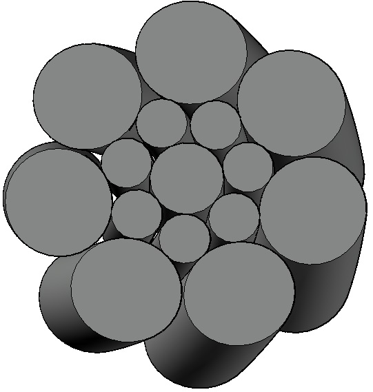
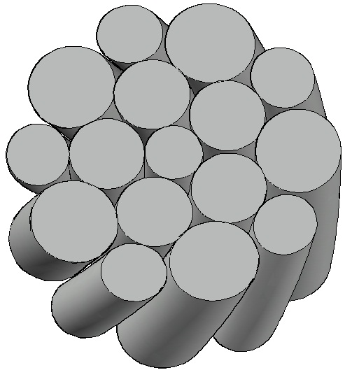
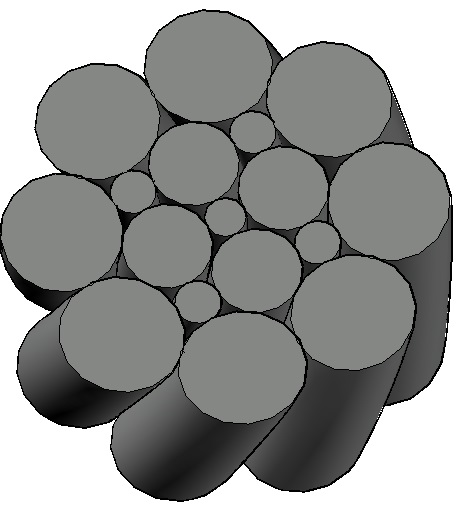
Ordinary lay
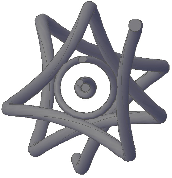
The above pictures show a 6X19/IWRC rope in cross section to illustrate the lay up of wires and the path they follow in an ordinary lay configuration.
WIRE PATH ANALYSIS
Parallel lays
Seal Construction
Multiple wire layers with the same number of wires in each layer
Warrington
Multiple layers of wires with an increasing number of wires per layer in the form N+N/N/1.
Filler
With multiple layers of wires in the form of 2N/Nf+N/1.
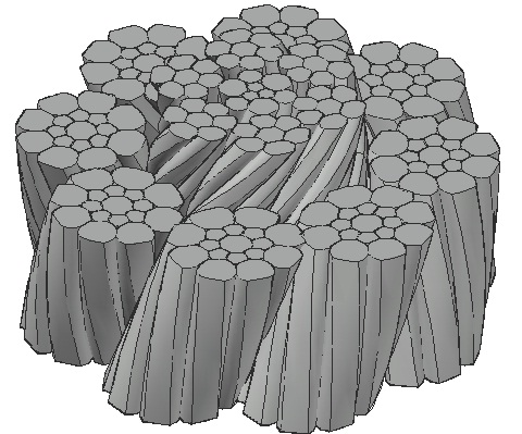
Lang lay

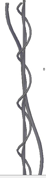
The pictures above show a right hand 6X19/IWRC rope in cross section and plan to illustrate the lay of wires with in the rope, the shape of the wires in cross section and the path the wires follow.
Strand and rope size calculation
Once the construction for the rope has been determined the calculation of the required wire sizes can begin.
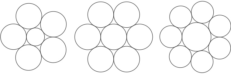
A simple sketch will show that six circles of the same diameter will fit around a seventh circle.
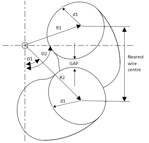
Wire sizes are selected such that there is a predefined gap between adjacent wires in each layer as is shown in the following sketch. Basic geometry can be used to "build" a strand from the inside out.

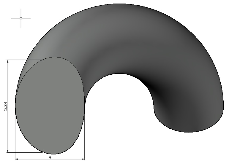
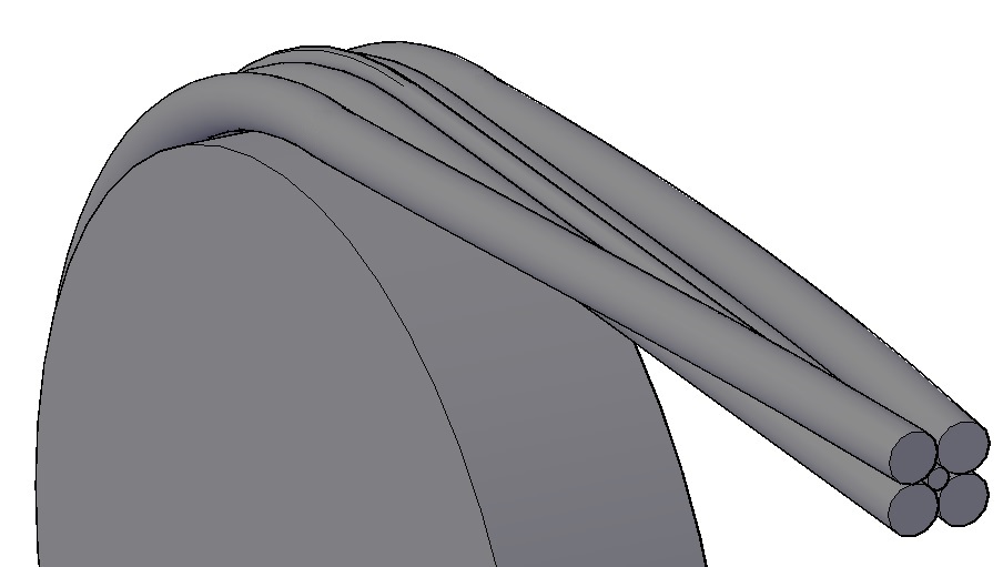
However, when the wires are twisted their cross section changes from being round to an ellipse for low lay angles and a bean shape when the lay angle becomes larger as shown below: (All the diagrams are based on a 4mm diameter wire)
This change in shape requires a little bit more calculation than basic geometry.
Finite Element Modeling

Rotation and Torque
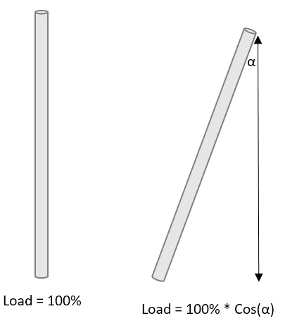
A bundle of parallel wires in a straight line will carry the load with a 100% efficiency. However when they bend over a sheave the pattern will crumble resulting in the wires damaging each other. The wires are therefore twisted into strands and the strands are twisted into ropes. This results in a loss in load carrying ability and the generation of torque which results in rotation.


Other Forces
Circumferential forces are created between wires and strands with in a layer which will reduce the ropes breaking force.
Radial forces are created by the outer wires and strands pushing in on the underlying wires and strands.
Rope Breaking Force
From the above it can be seen that the actual breaking orce is a factor of the agragate breaking force of the individual wires multiplied by a factor which takes into account the effects of twisting the strands and rope together.
Rope Torque
The rope torque is a factor which indicates what force is requires to prevent the rope from rotating when it is under load. This is estimated by calculating the torque generated by each wire in each strand and in each layer.
